I. Introduction
Knowing which insert has more edges doesn’t cut it when choosing between CNMG and WNMG inserts. If you pick the wrong choice, the roughing corners may chip, you may not be able to use all capabilities of the insert, or you may require a different toolholder. This article shows you the differences between them in real life and enables you to choose the correct one depending on cutting load, operation, machine setup and insert specification.
II. Understanding CNMG and WNMG Inserts
1. What Is a CNMG Insert?
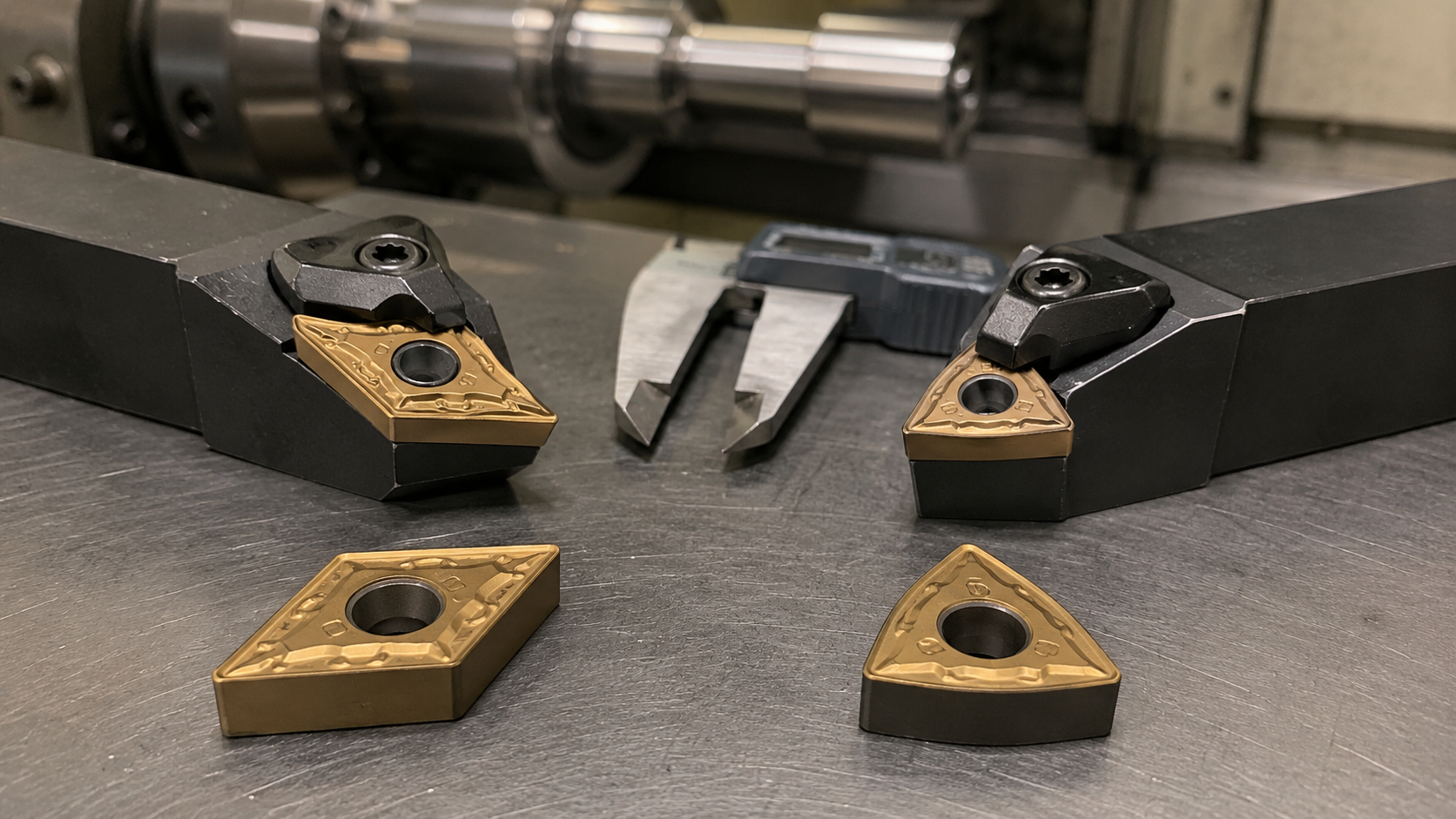
CNMG insert 80° rhombic, 0° clearance angle. Normally used as a double sided negative insert, it features two standard 80° cutting tips on each side for a total of four usable tips. It is not just the “N” letter that makes the cutting rake, but the toolholder, chipbreaker and edge preparation all together make the genuine cutting rake.
2. What Is a WNMG Insert?
The inserts are triangular with three 80° points on each side. It has a 0° gap so you can use both sides. This means that the insert has six cutting edges of the same type. It’s triangular shaped, however instead of the 60 degree TNMG insert, all three functional corners are 80 degrees.
III. Key Differences Between CNMG and WNMG Inserts
1. Rhombic Shape vs. Trigon Shape
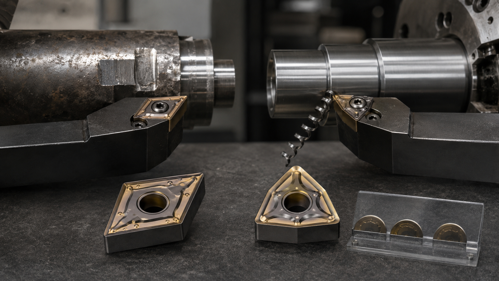
CNMG has an 80° rhombic insert with two 80° and two 100° corners on each side. The WNMG is triangular with three sides of 80°. Both have the same working nose angle but different design mean different edge length available, number of standard cutting tips, insert seat and compatible toolholder.
2. Four Cutting Tips vs. Six Cutting Tips
A CNMG insert contains four standard 80° cutting tips. A WNMG has six. The 100° corners on a CNMG are not used like the four normal tips, but customised holders can use them for specific face or scale removal treatments. The WNMG has 6 similar 80° tips, no second holder is needed to reach another corner type.
3. Effective Cutting-Edge Length
Common inserts such as CNMG 120408 and WNMG 080408 feature an inscribed circle of 12.7 mm, thickness of around 4.76 mm, nose radius of 0.8 mm. However, the effective cutting edge length is approximately 12.1mm for the CNMG example and 8.4mm for the WNMG example. This difference is important in the event of large depth of cut where more of the cutting edge is in contact with the workpiece.
4. Insert Body and Edge Support
The longer side of a CNMG leaves a continuous length of insert material in the wake of the working edge. A WNMG has three working tips that fit about the same basic body size, hence each cutting edge is shorter. They both feature strong 80 degree corners but the layouts give different amounts of usable edge for the cut.
5. Toolholder Compatibility
CNMG and WNMG inserts require separate compartments and toolholders. Same thickness, same nose radius, same inscribed circle criteria do not make them interchangeable. To shift from one shape to the other you need to confirm the holder, seat, shim, clamp, entering angle and cutting direction.
6. What the Insert Shape Does Not Decide
The C or W shape alone will not determine chip control, surface smoothness, cutting force, work piece compatibility, vibration or tool life. These results are also dependent on the chip breaker, grade, coating, nose radius, holder angle, cutting data and setup rigidity. For example, WNMG is not always a finishing insert and CNMG is not always ideal for all heavy cut.
IV. How to Choose Between CNMG and WNMG Inserts
1. Start with the Cutting Load
Start with CNMG if you need a significant depth of cut, high material removal or a heavily loaded cutting edge. If stock allowance is constant and the cut is in the medium operating range WNMG should be employed. The limit is dictated by insert size, entry angle, chipbreaker and effective cutting-edge length, hence no general agreement on a 3 mm changeover point exists.
2. Check Whether the Cut Is Continuous
WNMG is suitable for continuous turning under stable load conditions in which all six tips can wear normally. The safest bet for forged surfaces, scale, key ways, interrupted diameters, or irregular stock is almost always starting with the CNMG. The last insert should still be of a robust grade and have an edge preparation suitable for interrupted engagement.
3. Confirm the Required Cutting-Edge Length
Check the proportion of the cutting edge that will be in contact with the work at the maximum depth of cut. The needed length changes with the entering angle of the holder, hence the programd depth cannot be directly compared with the insert edge without taking the holder into account. If the WNMG cutting edge is too small, use the next bigger WNMG size, or switch to CNMG.
4. Check the Operation and Holder Angle
Both inserts can be used for longitudinal and face turning. The holder angle influences if the tool is able to reach a 90 degree shoulder, how forces are transferred into the workpiece and in what directions the feed is available. If the component is narrow in profile or if a lot of back turning is necessary then then neither CNMG nor WNMG may be able to offer appropriate access. A smaller nose angle insert may be required.
5. Consider Machine and Workpiece Rigidity
Don’t choose CNMG just because a setup is vibrating. Both CNMG and WNMG have powerful negative 80° type tips that can provide high cutting forces. For slender shafts, thin walls, long overhand on tool or low stiffness machines, reducing the nose radius, adjusting the entry angle or employing a positive insert may be more effective than moving from C to W forms.
6. Match the Grade to the Workpiece
Steel, stainless steel and cast iron can all be machined with either shape. The carbide grade and coating is decided by the workpiece material, not directly by CNMG or WNMG. You might use WNMG for stable medium turning in alloy steel and change to CNMG when the same material is rough, interrupted or uneven.
7. Match the Chipbreaker to the Operation
Use a finishing chipbreaker for mild depths of cut and lower feed, a medium chipbreaker for general turning and a roughing chipbreaker for heavier engagement. CNMG does not automatically evacuate the aggressive roughing chips better. WNMG does not automatically create smoother chips in semi-finishing. Chip control is improved only if the feed and depth of cut fall within the range for which the chipbreaker is designed.
8. Select the Nose Radius
Typical ISO nose radius designations are 04 for approx 0.4 mm, 08 for 0.8 mm and 12 for 1.2 mm. A bigger radius will improve the tip strength and the possibility of a larger feed, but also the radial force and the risk of vibration. Use a smaller radius for light cuts, skinny workpieces and less rigid setups, and a wider radius for sturdy setups and cutting loads that require more support on the edge.
9. Make Sure All Cutting Tips Can Be Used
The largest practical advantage of the WNMG is available when the set-up is stable enough to use all six tips. If the insert is breaking before regular wear and tear, more tips aren’t going to fix the problem. Though it has fewer typical 80° tips, CNMG may be more reliable if the operation demands additional edge length and support.
V. What Happens If You Choose the Wrong Insert?
1. The Cutting Corner Chips before Normal Wear Develops
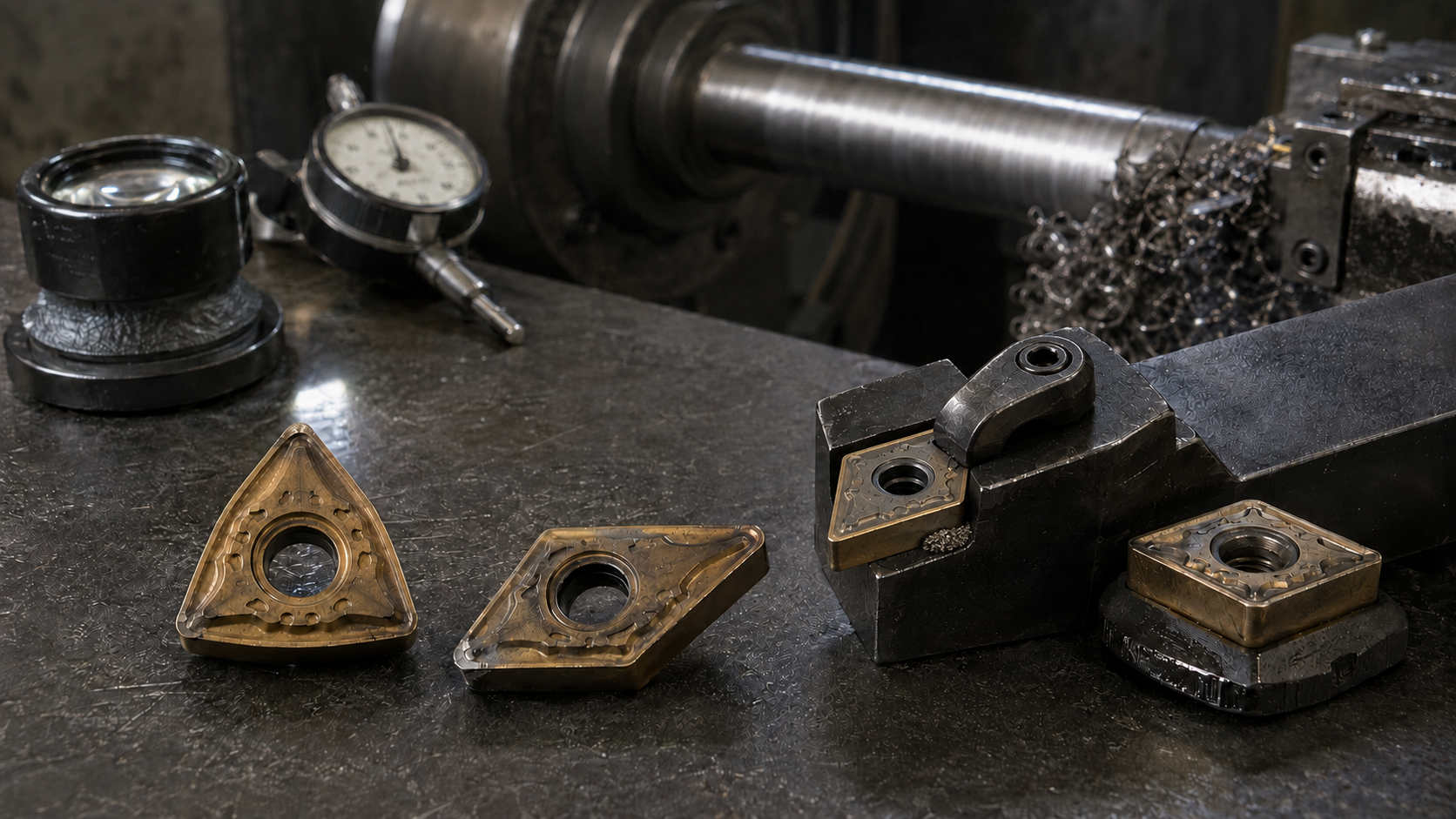
In heavy or interrupted cutting, if a WNMG corner chips repeatedly the insert may not be providing enough useful edge or support for the current load. Alternatively, you could lose the balance of the life of that corner before typical flank wear occurs, making it hard to regularly use all six available tips.
2. The Insert Capability Is Not Fully Used
If a CNMG is only making steady medium cuts which are using only a small portion of the longer cutting edge, there may be more load capacity in the insert than the operation requires. The machining output can be adequate, but, a WNMG would do the same procedure and provide two more 80° tips.
3. The Insert Moves inside the Toolholder
CNMG in a WNMG holder – or wrong seat, shim or clamp – will not allow the insert to locate properly. The outcome can be a change in tool position, poor surface finish, broken pockets or unexpected insert breakage in load.
4. Chips Wrap around the Part or Tool
Poor chip control does not indicate the CNMG or WNMG was shaped incorrectly. Often the chipbreaker, feed or depth of cut are found to be out of their intended range. If simply the insert form is changed, the same chip issue may persist.
5. Chatter Appears during Finishing
If vibration occurs following insert change, check nose radius, holder angle, tool overhang, and workpiece support. Both CNMG and WNMG are good 80° tips, therefore one can not eliminate chatter because of excessive radial force or inadequate setup rigidity.
6. Surface Finish Changes after Indexing
A major change in dimensions or finish after switching to a new cutting tip can indicate chips under the insert, a worn shim, a damaged pocket or inconsistent clamping. The amount of possible tips is only valuable if every indexed corner returns to a stable cutting position.
VI. Final Recommendation
Pick CNMG for heavy roughing, wider depths of cut, interrupted surfaces and jobs needing a longer supported cutting edge. For medium turning stability, use WNMG, the six 80° tips can be employed regularly. Both can do general OD and face turning, so check the holder angle and toolpath also. After the shape is chosen, fit the chipbreaker, carbide grade, coating, nose radius and insert size to the workpiece and cutting conditions. Send us your material, operation, maximum depth of cut, feed, holder model and present wear problem and we can assist with narrowing the option.
VII. FAQs About CNMG and WNMG Inserts
1. Can the 100° Corners of a CNMG Insert Be Used?
Yes. The 100° corners can be used by specialist holders for special facing or scale removal jobs. They can not be indexed and used just like the 4 conventional 80° corners in a normal CNMG-holder.
2. Does a CNMG Insert Have Four or Eight Cutting Tips?
Physically a double sided CNMG has four 80° and four 100° corners. A typical CNMG turning holder will usually provide you with four usable 80° tips.
3. Are CNMG 120408 and WNMG 080408 the Same Size?
Both can have a 12.7 mm inscribed circle, 4.76 mm thickness and 0.8 mm nose radius. They still differ in their overall form, cutting edge length, seating and holders.
4. Can CNMG and WNMG Use the Same Toolholder?
Both can have a 12.7 mm inscribed circle, 4.76 mm thickness and 0.8 mm nose radius. Still they differ in their general form, the length of their cutting edges, their seats and their holders.
5. Can You Keep the Same Cutting Data after Changing Insert Shape?
Don’t just assume the same data will work anymore. Start with the suggested range for the new insert grade and chipbreaker, then fine tune it according to load, chip formation, wear and setup stability.
6. Can a WNMG Insert Be Used for Roughing?
Yes, WNMG can rough when the required load is met in size, chipbreaker, grade and cutting-edge length. It should not be used as a finishing only insert.
7. Is 3 mm the Maximum Depth of Cut for WNMG?
No, there is not a generic limit of 3 mm. The depth capacity of some WNMG roughing geometries is bigger, however the permissible range is a function of insert size, holder angle, grade and chip breaker.
8. Can CNMG Be Used for Finishing?
Yes, a CNMG with a finishing chipbreaker and the correct nose radius can do finishing cuts. The surface outcome is more dependent on geometry, feed, nose radius, runout and stiffness than on the C shape alone.
9. Are Wiper Geometries Available for Both Shapes?
Yes, wiper geometries may be produced on both CNMG and WNMG. Make sure the edge of the wiper is oriented correctly to get the finish you want. Check the feed range you want to utilise and the orientation of the tool.
10. Why Does a WNMG Insert Chatter?
Possible causes are: too large a nose radius, too much overhang, entrance angle not suitable, weak support of the workpiece, or cutting data beyond the stable region. Chatter produced by the equipment or the configuration will not be solved by replacing WNMG with CNMG.
11. Why Does a CNMG Insert Produce Long Chips?
Long chips are frequently a sign that feed and depth of cut are beyond the working range of the chipbreaker. Changing the insert shape is less successful than picking the right chipbreaker and modifying the cutting circumstances.
12. Does CNMG Always Last Longer than WNMG?
No. CNMG is more reliable in heavily loaded or interrupted cuts whereas WNMG can do similarly well in stable medium turning. Edge failure mode determines tool life, not just insert shape.
13. Can PVD- and CVD-Coated Grades Use Both Shapes?
Yes, CNMG and WNMG are available in both PVD and CVD coated grades. Select the coating and the substrate according to the workpiece, operation, cutting circumstances and the needed balance between wear resistance and toughness.
14. Which Toolholder Codes Are Common for CNMG and WNMG?
Common external holders include PCLNR or DCLNR style for CNMG and MWLNR or DWLNR type for WNMG. The whole holder code still needs to be verified for insert size, cutting direction, shank size and entry angle.
15. What Should You Check before Replacing CNMG with WNMG?
Check the maximum depth of cut, cutting edge length, the needed continuity of cut, the holder angle, the power available in the machine and the rigidity of the workpiece. You also need to change (or check) the matching holder, since the two shapes cannot share a standard insert pocket.